A custom filter cartridge project usually starts with a media sample and a target efficiency. That is the wrong starting point for manufacturing. The housing interface decides whether the cartridge can be installed, sealed, and removed without damage. The drawing package should begin with the tube sheet or housing bore, the sealing surface, the available insertion depth, and the clamp or hold-down method. A cartridge that fits the media spec but misses the bore tolerance by a few tenths of a millimeter can fail at installation. The first drawing should be a dimensioned section through the housing, not a sketch of the filter. That section should show the sealing land, the stop shoulder, the clearance around the cage, and the path used to slide the cartridge in. Without that drawing, the cartridge design is a guess.
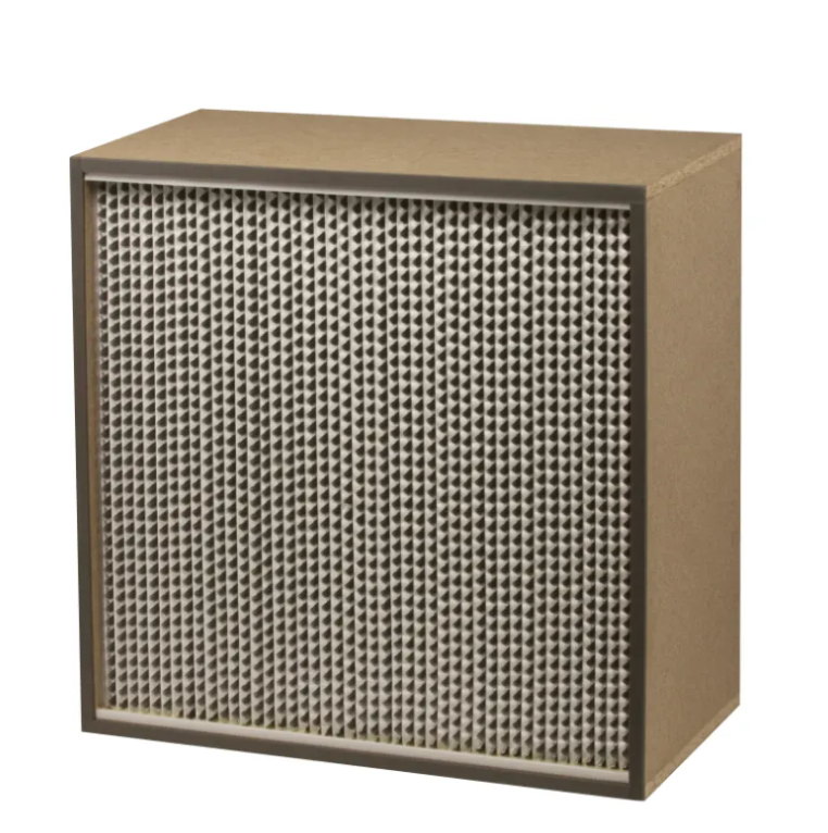
The end cap and gasket are where most custom cartridge problems show up. The drawing should define the gasket groove or land, the compression height, the end cap outer diameter, and the bond line between the media pack and the cap. A tolerance stack that looks fine on paper can leave the gasket under-compressed or over-compressed. Over-compression can distort the cap and open a leak path. Under-compression can pass a visual check and leak in service. The end cap drawing should also show the cage attachment and the media pack orientation. If the cartridge has a molded gasket, the tooling split line and draft angle belong on the drawing. If the gasket is a separate ring, the groove dimensions and the gasket hardness should be on the spec sheet. These details are not decorative. They are the difference between a cartridge that seals and one that needs a field fix.
A custom filter cartridge is not one material. It is a set of materials that must work together. The spec sheet should list the media grade, the support layer, the cage material, the end cap resin, the gasket elastomer, and the adhesive. Each line should include the operating temperature, the chemical exposure, and the cleaning method. A media that handles the dust but not the cleaning chemical can fail early. A gasket that seals air but swells in solvent can create a leak. The table below shows the drawing and spec items that should be closed before a quote is meaningful.
| Drawing or spec item | Why it matters | Common gap |
|---|---|---|
| Housing section with sealing land | Sets insertion and compression | Sent as a photo, not a dimension |
| End cap and gasket groove drawing | Controls seal compression | Groove depth left to supplier guess |
| Media grade and support layer | Sets dust release and strength | Only efficiency class given |
| Cage and pleat pack dimensions | Controls fit and bypass | Cage omitted from drawing |
| Gasket elastomer and hardness | Controls chemical compatibility | Hardness not specified |
| Adhesive and bond line | Controls media to cap strength | Bond width not shown |
| Operating temperature and cleaning | Sets material limits | Only normal condition listed |
The table is a checklist, not a wish list. Each missing line becomes a question during production, and questions cost time.
Tolerances sent in an email tend to disappear when the drawing reaches the shop floor. The cartridge drawing should carry the critical dimensions with clear tolerances, and the datums should match the housing interface. ASME Y14.5-2018 is a useful reference for geometric dimensioning and tolerancing, and it forces the drawing to state what is actually controlled. A roundness callout on the end cap, a perpendicularity callout on the sealing face, and a profile tolerance on the gasket groove all matter more than a general note. The drawing should also mark the inspection dimensions. Not every dimension needs a gauge, but the sealing land, the cap diameter, and the insertion length should be measurable. If the drawing cannot be inspected, the tolerance is a suggestion.
The mechanical drawing does not describe the process. The spec sheet should state the design airflow, the expected dust loading, the cleaning method, and the pressure drop limit. These numbers set the media area, the pleat count, and the cage strength. A cartridge designed for a light dust load can collapse under a heavy cake if the cleaning pulse is strong. A cartridge designed for a high airflow can run at a higher face velocity than the media can handle. ISO 16890 is useful for classifying general air filters, but it does not replace a project specific dust load review. The spec sheet should also state the installation orientation and the access space for removal. A cartridge that fits but cannot be pulled out is still a design failure.
A drawing package is a hypothesis until a first article is built and fitted. The first article should be checked against the housing section, the sealing land, and the clamp. A field fit check is worth the time, especially on retrofit projects. In a chemical plant retrofit in southern China, the first batch of custom filter cartridges was built from a housing sketch that omitted the tube sheet opening and the sealing surface roughness. The cartridges fit the bore but did not compress the gasket evenly. The fix required a revised end cap drawing and a new gasket groove. The lesson was simple: the housing drawing is part of the cartridge drawing package. For projects that need consistent fabrication, batch level material control, and a supply chain that can match housing interfaces, Renhe's production base and quality control process can support the drawing review and first article side of the work. A custom cartridge design is only as good as the dimensions it is built to.
 Hot News
2026-11-13
2026-11-13
2026-11-13
2026-11-13
2026-11-13
2026-11-12
Renhe focuses on air filter cartridge, gas turbine air filter, Pleated Filter Media, industrial dust, Our main products have been recognized as high-tech products in Jiangsu Province, famous trademarks in Wuxi City, and CE certification.
NO. 31 Xingyuan Road, Jiefang Industrial Park, Gushan Town, Jiangyin City, Jiangsu Province, China (214414)
Copyright © 2024 Jiangsu Renhe Environmental Equipments Co., Ltd Privacy Policy
 EN